Hydrodynamic Coupling MG-M-500

Other models

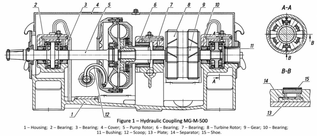
Hydrodynamic Coupling MG-M-500

Hydrodynamic couplings MG-M-500 are designed for manual and remote speed regulation of boiler feed pumps and other centrifugal pump units to control head and discharge in accordance with system network characteristics.

The hydrodynamic coupling is installed between a motor with a rated speed of 3000 rpm (synchr.) and a pump. Speed regulation is performed via a scoop tube control mechanism.

Main Technical Specifications

Parameter Value
Rated input power on driving shaft, kW 800
Driving shaft synchronous speed, s⁻¹ (rpm) 50 (3000)
Slip control range, % 2.5 – 80*
Gear ratio of the multiplier gear pair 3.0769
Gear tooth profile Novikov gearing
Lubrication type Forced pressure lubrication
Working fluid Turbine oil TP-22 (GOST 9972-74) or TP-22S
Weight, kg 1940
Overall dimensions (Length × Width × Height), mm 1730 × 1414 × 810

* Hydrodynamic coupling slip is calculated using the following formula:

S = ((n₁ – n₂) / n₁) × 100%

where:

S — slip

n₁ — driving shaft speed, rpm

n₂ — driven shaft speed, rpm

Hydrodynamic couplings MG-M-500 chart

Designation Structure

Hydrodynamic Coupling MG-M-500:

where:

  • MG — Hydrodynamic coupling (Mufta Gidrodinamicheskaya)
  • M — With built-in step-up gear (multiplier)
  • 500 — Active circuit diameter, mm

Operating Principle

The operating principle of the MG-M-500 hydrodynamic coupling is based on the hydrodynamic transfer of torque from the driving shaft to the driven shaft using the kinetic energy of the working fluid (TP-22 / TP-22S turbine oil), as well as on scoop-tube regulation of the working circuit filling level.

The rotational speed of the driven shaft and the transmitted power depend on the volume of oil present in the working cavity (working circuit). Speed control in the MG-M-500 hydrodynamic coupling is achieved via a scoop tube arrangement.